Matsya 1

Matsya 1 was the very first AUV designed by the team back in 2011, with a goal to develop a state of the art AUV that could localize itself in an underwater environment and complete some predefined real life tasks for the Robosub 2012 competition.

Specifications Vehicle Details
DoF 5 (Roll, Pitch, Yaw, Surge, Heave)
Weight 20 kgs
Dimensions 1000mm x 531mm x 337mm
Endurance 60 Minutes
Depth Rating 40 feet
Pressure Vessels One Hull for Electronics, Batteries and Camera.
Actuation System Assembly of Five thrusters
Power Lithium Polymer Batteries
Feedback Control Visual, Inertial, Pressure.

SPECS

    1. A Single Cylindrical Acrylic Hull with Aluminium End-cap to house all Electronics, Batteries and Camera
    2. The cylindrical design was conceived to minimise drag and Aluminium was chosen for the rear end cap to vent the heat through conduction.
    3. Keeping in mind modularity, static and dynamic performance,the frame was made using Al 8020

    1. The vehicle has five thrusters which give it 5 degrees of freedom, namely heave, surge, yaw, pitch and roll.
    2. The vehicle takes feedback from on-board Inertial Measurement Unit (IMU) which functions as an Attitude and Heading Reference System (AHRS), cameras and pressure sensors.

  • The vehicle can operate at a maximum velocity of 0.6m/s and weighs only 20kgs which made it the lightest vehicle to participate in Robosub 2012.

    1. The processing platforms are chosen based on the basic needs of vision processing, controls and power management, and are designed with an emphasis on modularity and scalability in the future.
    2. There are three main boards in the electrical stack:
      1. Power Board, which is an 8-bit microcontroller (Atmega 2560) that ensures the power management of the vehicle by aiding in battery management, temperature control, Water seepage Detection, Kill switches and Power Distribution.
      2. PandaBoardES is used for vision processing and communication to on-board processors serially and to off-board processors via Ethernet.
      3. The motion controller of the vehicle takes feedback from the inertial sensors, the pressure sensor, the SBC and controls the thrusters.

  • The final part of the electronics division are the sensors and actuators which consist of Pressure Sensor, Attitude Heading Reference System (AHRS), Cameras, Current Sensors, Actuators and driver.

    1. The software stack in Matsya 1 was responsible for mission planning, image processing, and handling the communication between the hardware modules, power board and motion controller board.
    2. We implemented Underwater Image Enhancement in Vision, which was built on Intel’s OpenCV library, and also implemented Color Contrast Stretching and Gate Pass Detection.
    3. The debugging platform of Matsya 1 was implemented using C, JavaScript and AJAX. Two cameras were used, a front camera for localization and a bottom camera for getting the orientation of the vehicle.

Matsya 2

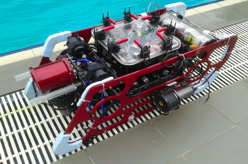
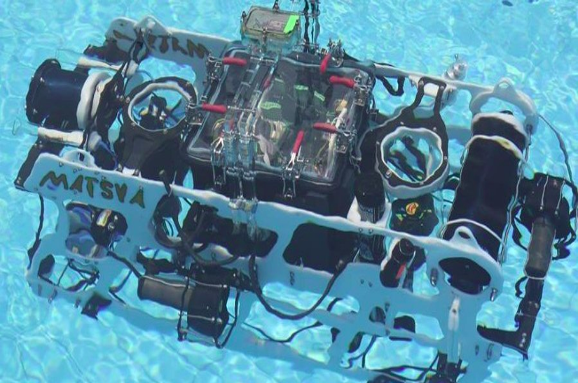
The second iteration of Matsya is complete and more modular than its predecessor, with separate enclosures for electronics, batteries, cameras, and torpedo shooting actuators. The design aimed to ensure robust waterproofing, ease of assembly, and efficient heat sinking.

Specifications Vehicle Details
DoF 5 (Roll, Pitch, Yaw, Surge, Heave)
Weight 24 kgs
Dimensions 930mm x 410mm x 650mm
Endurance 90 Minutes
Depth Rating 100 feet
Pressure Vessels Separate hulls for Electronics, Batteries, Camera and Hydrophones.
Actuation System Assembly of Six thrusters, Markers
Power Lithium Polymer Batteries
Feedback Control Visual, Inertial, Pressure

SPECS

    1. Matsya 2.0 has five degrees of freedom, with sway being a new addition.
    2. A cuboidal main hull with peripherals for better space optimization.
    3. The main hull houses the electronics of the vehicle, which are mounted on an acrylic rack. Al 6061 is used for the hull body due to its thermal conductivity, high strength, and non-corrosiveness.
    4. An acrylic end cap seals the hull using a latch mechanism, which uses an E-clip and O-ring.

    1. The frame acts as a mount for many peripherals.
    2. It has a bottom-heavy, open-frame design that exhibits high symmetry, modularity, and, most of all, stability.

  • The vehicle has a gripper, marker dropper, and torpedo shooter, all of which are actuated pneumatically.

    1. All the microcontrollers on the system have been separated out of the main electronics board using microcontroller caps. This approach provides the ease of microcontroller replaceability, off-board microcontroller programming and accumulating the same number of components in much less area.
    2. The dual-core 1.2GHz Arm cortex-A9 CPU, 384 MHz GPU, 1GB RAM PandaBoard ES SBC used in Matsya 1 was replaced by Axiomtek's SBC86860 Mini ITX motherboard with an Intel Core 2 Duo Processor clocked at 3.0 GHz and 4GB of RAM.
    3. Serial interface for a separate LCD has also been facilitated for debugging the algorithms running on Motion Controller. A separate pneumatic system has been developed in Matsya 2.0 for facilitating a separate path to allow large currents to be drawn from the battery when switching the six pneumatic valves separately.

    1. The Acoustic Localization Unit was introduced in Matsya 2.0, using hydrophones in the Ultra Short Base Line arrangement.
    2. This Is useful for the system to detect pingers at different frequencies. Atmel's 8 bit AT90CAN64 microcontroller has been used for power management replacing the 8 bit Atmega 2560.
    3. Additional features include RGB LEDs for battery status, extra power lines for scalability and JTAG interface from debugging perspective. We used VectorNav’s VN200 as IMU replacing the VN100 used in Matsya 1.0.

    1. A new codebase was designed to implement ROS, introducing several new features to the software stack.
    2. A Gazebo simulator was also implemented for simulation and testing of Matsya.
    3. Implementation of Mission Planner allowed us to plan our task execution resulting in better performance during competitions. The mission planner consisted of a finite state machine implementation along with the four nodes - Planner, Transition State, Scan State and Execution State.

Matsya 3

Matsya 3 was the third vehicle built by the team in 2013. Matsya-3 has a modular design and weighs 42 kg. It is highly optimised for strength and buoyancy.

Specifications Vehicle Details
DoF 5 (Roll, Pitch, Yaw, Surge, Heave)
Weight 44 kgs
Dimensions NA
Endurance 120 Minutes
Depth Rating 150 feet
Pressure Vessels Separate hulls for Electronics, Batteries, IMU and
Cameras.
Actuation System Assembly of Six thrusters, Markers and Torpedos.
Power Lithium Polymer Batteries
Feedback Control Visual, Inertial, Pressure and Acoustic

SPECS

    1. This version of Matsya saw the integration of a DVL (Doppler Velocity Log), which greatly improved the accuracy and flexibility in localisation.
    2. A major addition to the vehicle, separate enclosures were designed for DVL, Battery and IMU to provide modularity to the system.
    3. The new enclosure for IMU was made from acrylic to cut off electrical noise due to other Electrical components of the vehicle.

    1. A total of four grippers, and improved gripper design.
    2. Newly developed underwater connectors for connecting different hulls and thrusters.
    3. These connectors were cheap to manufacture and convenient to use.
    1. Matsya-3 has 6 thrusters capable of producing a total of 2.2 kgf of continuous thrust and a peak thrust of 2.9 kgf.
    2. The thruster mounts are designed in such a way that the thrusters do not produce any skin friction drag on the side frame of the vehicle.
    3. Due to this Maysta-3 has a maximum speed of 0.5 m/s and is capable of navigation along five degrees of freedom.

    1. Inertial Measurement Unit: The IMU used in Matsya 2.0 was VectorNav's VN 200 but this was replaced by 3DM-GX3-25 Attitude Heading Reference System (AHRS) from Lord Microstrain Sensing Systems in Matsya 3.0 due to its low-drift and precise orientation measurement.
    2. The new enclosure for IMU was made from acrylic to cut off electrical noise due to other Electrical components of the vehicle.

    1. A new ethernet based inter-board communication, and a new Navigator package to help bridge the gap between the Mission Planner and Controller.
    2. It provides a common platform where all task-executors can launch commands.
    3. The navigator is what steers the vehicle from point to point using feedback from localization.

    1. In vision, we implemented a new framework with OpenCV as a single C++ library with a single ROS Node to handle communication between Vision and the rest of the software stack.
    2. There was also an ML based object detection module consisting of a sliding window detector, feature vector extractors and classifiers.

    1. The new inertial measurement unit offers low drift and precise orientation measurement, and was enhanced with an acrylic enclosure to cut off disturbances from other electrical components in the system.
    2. Two additional grippers and an improved gripper design ensured greater functionality of the vehicle, along with newly manufactured, convenient and more cost efficient connectors for the different hulls and thrusters.
    3. Powered with six thrusters to produce a total of 2.2 kgf and a peak of 2.9kgf thrust, Matsya-3 was enabled with navigation along five degrees of freedom and could attain a maximum speed of 0.5m/s.

Matsya 4

Matsya 4 is the fourth AUV in the Matsya series. Although it has a similar design philosophy to Matsya 3, it has majorly improved in terms of weight optimization, reliability, endurance, speed, aesthetics, and cognition.

Specifications Vehicle Details
DoF 5 (Sway, Pitch, Yaw, Surge, Heave)
Weight 41.4 kgs
Dimensions 1070mm x 770mm x 550mm
Endurance 240 Minutes
Depth Rating 150 feet
Pressure Vessels Separate hulls for Electronics, Batteries, Cameras, IMU and DVL.
Actuation System Assembly of eight thrusters, Markers, Gripper and Torpedos
Power Lithium Polymer Batteries
Feedback Control Visual, Inertial, Pressure, DVL and Acoustic

SPECS

    1. Two battery hulls which increased the vehicle's Endurance Time to 240 minutes.
    2. Separate hulls for Electronics, Batteries, Cameras, IMU and newly designed DVL hulls are used.

    1. High voltage (30V) rated thrusters were chosen for surge direction in order to provide a higher surge speed.
    2. The outdated intel core 2 was replaced with the latest i7 processor.
    3. The vehicle also got a redesigned control system to provide 5 degrees of freedom (surge, sway, heave, pitch and yaw).

    1. The optimization process has been divided into two parts: Unit optimization and integrated optimization.
    2. In unit optimization, only the sub-assembly was optimized on the basis of weight, strength, impact resistance, and space.
    3. While in the integrated optimization, the entire assembly of Matsya was optimized.

    1. The camera was upgraded to a newer version, the number of hydrophones were increased from 2 to 4.
    2. Based on power requirements the initial 2x 6.6Ah 4 cell was changed to 2x 16Ah 5 cell.
    3. The signal sampling device was upgraded to a more robust NI9223.
    4. The pressure sensing and motion controlling board were incorporated into a single GPIO board.
    5. DVL and Acoustic Localization systems were incorporated into the navigation framework.

    1. A cascaded control architecture consisting of a kinematic and a dynamic controller was developed.
    2. This kinematic-dynamic controller pair achieved both global position and velocity control using reference tracking.
    3. A 3D motion simulation tool was used to test motion planning, navigation, and performance of the motion controller.

Matsya 5

Matsya 5 is the fifth AUV in the Matsya series. To permit easier access to the components of the vehicle, the surface was split into 6 parts, each of which was detachable.

Specifications Vehicle Details
DoF 6 (Roll, Pitch, Yaw, Surge, Sway, Heave)
Weight 47 kgs
Dimensions 1750mm x 780mm x 640mm
Endurance 240 Minutes
Depth Rating 150 feet
Pressure Vessels Separate hulls for Electronics, Batteries, Cameras, IMU and DVL.
Actuation System Assembly of eight thrusters, Markers, Gripper and Torpedos
Power Lithium Polymer Batteries
Feedback Control Visual, Inertial, Pressure, DVL and Acoustic

SPECS

    1. A total of 8 thrusters have been used in Matsya 5 as compared to Matsya 4 in which 6 thrusters were only used .
    2. These 8 thrusters provide all possible 6 degrees of freedom to the vehicle.
    3. The centroid of the isosceles triangle of heave thrusters, the midpoint of the sway thrusters and the Centre of Gravity (CG) of the vehicle have been made collinear for maximum overall stability.

    1. Matsya 5 has only one gripper mounted on the right side of the frame. Matsya 4 had two grippers, one on each side of the frame.
    2. Matsya 5 has two marker droppers and the actuation system has been optimized to use only one pneumatic piston as opposed to two in Matsya 4A.

    1. A Dynamic Mission Planner was implemented that is capable of switching tasks in between based on the feedback from vision.
    2. The Mission Planner design was also changed to provide more layers of abstractions, thereby creating a more modular structure that made writing tasks easier and less error-prone.
    3. The modular structure was achieved by grouping all tasks related to one physical object as subtasks of one parent task.
    4. Whenever the parent task is executed, the vehicle scans for the corresponding physical object. When the object is found, the vehicle executes each of the subtasks one by one.
    5. The state machine was shifted to a probabilistic model, where the decisions are based on the probability of pose detection from vision.
    1. Added CAN communication system for more robustness. In the motor driving board, we used 8 BlueESC from BlueRobotics.
    2. Instead of Beagle-Bone Black (ARM Cortex-A8 processor), we used Atmega328p on the GPIO board.
    3. We built our transmission and receiver system on UART for communicating between two vehicles.
    4. In addition, safety features such as reverse battery voltage protection, over-current protection and soft kill for thrusters are also added.

    1. The Navigator module’s algorithms were improved to break down set points to minimize the time taken in transition from one point to another with an auto timeout being implemented by estimating the time for transition.
    2. The DAQ system used to collect acoustics data from the hydrophones was earlier run on a virtual machine running Windows (as that is the only OS supported by the manufacturer).
    3. It was reverse engineered in Matsya 5 to enable us to run it natively on Ubuntu, thus improving speed and eliminating the stability issues arising from VM.

Matsya 6

The sixth variant of Matsya saw major design changes to address pressing issues such as heating leading to multiple electrical failures and reducing the size of the vehicle in general for better control.

Specifications Vehicle Details
DoF 6 (Roll, Pitch, Yaw, Surge, Sway, Heave)
Weight 37 kgs
Dimensions 1051mm x 442mm x 609mm
Endurance 240 Minutes
Depth Rating 150 feet
Pressure Vessels Separate hulls for Electronics, Batteries, Cameras, IMU and DVL.
Actuation System Assembly of eight thrusters, Markers, Gripper and Torpedos
Power Lithium Polymer Batteries
Feedback Control Visual, Inertial, Pressure, DVL and Acoustic

SPECS

    1. The bringing of PWM signal wires through a separate penetrator reduced interference and attenuation significantly.
    2. The latest variant of Matsya has cylindrical battery hulls, as opposed to cuboidal hulls used in the previous iteration.
    3. This particular change helped reduce disassembly time considerably, thus increasing the ease of removing the batteries for recharging.
    4. A dome structure has been added on the front-facing plane of the hull to reduce drag.
    5. Heavy parts bearing regions have been designed such that the load-bearing capacity in the vertical direction remains high.

    1. The vehicle has 8 thrusters, which makes movement in all the six DOF (Degrees Of Freedom) achievable.
    2. It also has other manipulation systems, namely the arm, the gripper, torpedo shooter, and the marker dropper (which has a reloading capacity).
    3. The latter two are actuated using high-pressure pneumatic actuators.
    4. The 1 DOF arm's split-finger gripper is also actuated by a pneumatic actuator.

    1. It has been installed for easier debugging and management of the electrical subsystem of the machine.
    2. The Debug Board’s job is to capture data from various parts of the machine, like the electrical stack, PWM Channels, thruster current values from the ESCs, and the motherboard itself.
    3. The Debug Board sends data to the motherboard for any real-time decisions that would need to be made and stores it in the SD card for future analysis.
    4. It also displays the data on an LCD screen for easier debugging.

    1. Developed a framework for Dynamic Modelling of the vehicle for further development in controls, localization, and simulation.
    2. We also implemented a MIMO Linear Quadratic Regulator (LQR) Controller to replace our 6 SISO PID Controllers.
    3. Mission planner was also simplified to take minimal parameters just before deployment, making it very competition-friendly.
    4. The decision-making process is almost linear, and it inherits task-grouping from the previous design.
    5. A New Artificial Potential Field based Path Planner was developed for obstacle avoidance.
    6. A plugin was developed for Gazebo to automatically detect tasks in the camera frame and draw bounding boxes around them for ML training. This labelling process was previously done manually and took a long time due to the size of the dataset (~1000 images per task).

    1. A new hull, the ESC Hull has been designed exclusively for ESCs (Electronic Speed Controllers) that would house all the ESCs along with the related circuitry.
    2. A power distribution box to avoid wire clutter was added along with a mechanical latch relay which implements Hard-kill by physically disconnecting the batteries should there be any failures.
    3. Real-time current and PWM monitoring is done for the thrusters so that any issues can easily be resolved and debugged.